Archive for the ‘ PLC ’ Category

MBOC Installing

Please note this does not apply to the newer QxUD range, as it isn’t required.

MOBC is multiple block online change. When you are doing a online program change MBOC will allow for larger change to be done, or more smaller changes, without needing to redownload the PLC code. The MBOC reveres a sections of space at the end of program, which is shuffles me code into.

This is done by (noting that the below complete wipe all program, variable and parameters).

  • Selecting the “Online” dropdown menu
  • Selecting “Format Drive”
  • The following popup will appear
  • Make sure that the MBOC is set to 4K Steps, and then select “Format”

To check if a PLC has had the MBOC set up, you need to go

  • Select the “Online” dropdown menu
  • Select “File Info” option
  • If the highlight option shown below (MBOC.QMB) is in the list then MBOC has been correctly implemented

Modbus Ethernet Slave Address Mits

Switch setting are for switch 2 – 0004

Switch 3 and 4 are the IP address octives converted into HEX

Switch 1 and 5 are all zero

Modbus address relocate

Mitsubishi Modbus To Comap CHP

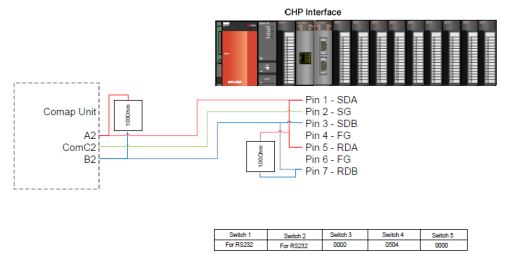
The below wiring diagram shows the QJ7MB91 modbus card linking to the RS485 port on the Comap unit of the CHP. Noting that the Comap unit needs to be set to RS485 as well.

CHP Interface

Noting the setting on the Comap where 9600, none, 8 bits and one stop bit. With the PLC working as the master unit.

The comms switch are broken down in page 159 of the manual, but a rough overview is below.

  • Switch 1 and 2 are used for Modbus over RS232
  • Switch 3 – set to all 0000 for master on the network
  • Switch 4 bit 1 and 2 (05) determine the speed of the comms
  • Switch 4 bit 3 and 4 (04) determine the other settings (parity, stop bit etc)
  • Switch 5 determine the modbus address (bit 1&2 for RS232 and bit 3&4 for RS485), if master these should be set to 00.

Since the PLC is operating as master on this network, if set correct you’ll get the SD, and RD (because their link) lights flashing as well as the NEU.

A useful link is to Mitsubishi card search results.

I’ve also link in the manual here: QJ71MB91

Uploading Register In GX IEC Developer

To upload tag values in GX IEC Developer:

  • Make sure you can get online
  • Go “Debug” – “Device Edit…”

Debug Menu

  • Right click and select add device, then select variables that you would like to add
  • Select “Read From PLC…”

device edits

  • Then select either to read selected values or all
  • Then chose to “Write to File”, selecting location etc that you want

Issue Doing Export From RSLogix 5000 To Network Drive

If you attempt to do a export from RSLogix 5000 to a network drive (i.e. host machine while working in virtual box), this creates a 0kB file which can’t be reimported, therefore the file must always be exported to the local computer and moved across.

RSLinx Won’t Recognize PLC, PLC is Showing Up As Unknown

If RSLinx can see the PLC, however is showing it as an unknown device, this can be solved by the following:

  • Open up RSLinx Classic (in case you where doing Who Online in RSLogix 5000)
  • Select Who Online Line
  • Browse your Ethernet Driver Network
  • Select the unknown device, should be showing as a question mark
  • Right click on the device
  • Select upload EDS Driver
  • Follow the wizard through, and upload the driver, now the device should be recognized

This fault was caused by RSLinx not having the correct firmware to talk with the PLC / Ethernet card.

You can also download the drivers from Rockwell’s website/


PID Setup Bit In RSLogix 500

The following is bit and int setup data for setting up PID in an SLC. Noting that some of the text is taken from the help manual.

Control Word 0, bits 7 (DA – Derivative Rate Action bit) and 4 (RG – Reset and Gain Rate Enhancement bit)apply only to the SLC 5/03, SLC 5/04, and SLC 5/05 processors and to the MicroLogix 1500 controller.

Word Description
1 PID Sub Error Code (MSB)
2 Setpoint SP
3 Gain Kc
4 Reset Ti
5 Rate Td
6 Feed Forward Bias
7 Setpoint Maximum (Smax)
8 Setpoint Minimum (Smin)
9 Deadband
10 Do NOT Use
11 Output Max
12 Output Min
13 Loop Update
14 Scaled Process Variable
15 Scaled Error SE
16 Output CV% (0-100%)
17 MSW Integral Sum 5/03/Micro 1500 MSW Integral Sum
18 LSW Integral Sum 5/03/Micro 1500 LSW Integral Sum
19 Altered Derivative Term (Low word)
20 Altered Derivative Term (High word)
21 Time of Last Update
22 Setpoint Old Value

Word 0 is broken up into bits, as per the following

Word Description
0 Time Mode Bit TM(word 0, bit 0) Specifies the PID mode. It is set when the TIMED mode is in effect. It is cleared when the STI mode is in effect. This bit can be set or cleared by instructions in your ladder program.
1 AM Auto/Manual Bit (word 0, bit 1) Specifies automatic operation when it is cleared and manual operation when it is set. This bit can be set or cleared by instructions in your ladder program.
2 CM Control Mode Bit (word 0, bit 2) This bit is cleared if the control is E=SP-PV. It is set if the control is E=PV-SP. This bit can be set or cleared by instructions in your ladder program.
3 OL Output Limiting Enabled Bit (word 0, bit 3) This bit is set when you have selected to limit the control variable. This bit can be set or cleared by instructions in your ladder program.
4 RG Reset and Gain Rate Enhancement Bit5/03, 5/04, and 5/05 only (word 0, bit 4) When set, this bit causes the Reset Minute/Repeat value and the gain multiplier to be enhanced by a factor of 10, (reset multiplier of 0.01 and gain multiplier of 0.01When clear, this bit allows the Reset Minutes/Repeat value and the Gain Multiplier value to be evaluated in the same units as the 5/02 PID instruction, (reset multiplier of 0.1 and gain multiplier of 0.1)Note that the Rate multiplier is not affected by this selection.
5 SC Scale Setpoint Flag (word 0, bit 5) Cleared when setpoint scaling values are specified.
6 TF Loop Update Time Too Fast (word 0, bit 6) This bit is set by the PID algorithm if the loop update time you have specified cannot be achieved by the given program (because of scan time limitations).If this bit is set, try to correct the problem by updating your PID loop at a slower rate or move the PID instruction to an STI interrupt routine. Reset and rate gains will be in error if the instruction operates with this bit set.
7  DA Derivative (Rate) Action Bit 5/03, 5/04, and 5/05 only (word 0, bit 7) When set, this bit causes the Derivative (Rate) calculation to be evaluated on the error instead of the PV. When clear, this bit allows the Derivative (Rate) calculation to be evaluated the same as the 5/02 PID instruction, (where derivative is performed on the PV).
8  DB Deadband Error (word 0, bit 8) Set when the process variable is within the 0 crossing deadband range.
9  UL Output Alarm, Upper Limit (word 0, bit 9) Set when the calculated control output CV exceeds the upper CV limit.
10  LL Output Alarm, Lower Limit (word 0, bit 10) Set when the calculated control output CV is less than the lower CV limit.
11  SP Setpoint Out of Range (word 0, bit 11) Set when the setpoint exceed the maximum scaled value or is less than the minimum scaled value.
12  PV Process Variable Out of Range (word 0, bit 12) Set when the unscaled (or raw) process variable exceeds 16383 or is less than zero.
13  DN PID Done (word 0, bit 13) This bit is set on scans where the PID algorithm is computed. It is computed at the loop update rate.
14  ??????????????????
15  EN PID Enabled (word 0, bit 15) This bit is set while the rung of the PID instruction is enabled.

Mits Setup For Serial Comms

To connect to Mits PLC, you require a Mits programming lead (the red one).

  • Connect the cable from computer RS232 serial port to the serial port on the processor.
  • Open up GX IEC Developer
  • Click on the Online drop down menu, and select Transfer Setup and then Ports
  • Click on Serial USB, Select RS-232C, Select COM port 1 or 2 depending on which channel matches what you chose on the serial card. Transmission speed 115.2 Kbps is normally OK Click OK

  • Click on PLC Module – Leave PLC Mode as Default

  • Click on No Specification and then OK (leave settings as default)

  • Click on Connection Test – If settings are correct and cable is fitted correctly, a connection successful message will appear. If connection is fine, Click OK.


FlexIO Expasion Rack

The FlexIO when having the rack expanded follows the cable, so if the cable plugs into the right side the rack number goes right to left.

CompactLogix Rack Expansion

When using the expansion racks in Compactlogix, the racks are read left to right, no matter which direction the cable goes. As demonstrated below. Please note the below setup won’t work from it is missing PSU.